OMT20 SX/DXN
Summary
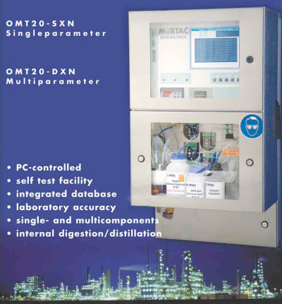
The On Line analyzer OMT20-SXN has been designed as a single components wet chemistry analyzing system, whereas the OMT20-DXN allows analysis of multi-components. Controlled by an Industrial PC of robust design, the precise dosage elements ensure the execution of analysis with both laboratory accuracy and high reproducibility. The OMT20-SX/DXN is suitable for installation in measuring rooms, laboratory surrounding and clean production centres. The control software is of a strictly modular and object-orientated kind.
System components
Control unit
- Control computer (Industrial PC without fan cooling)
- VGA LCD 10,4” color monitor
- Service interface (Mouse/Keyboard - connection)
Analytic part
- Sample dosage
- Measuring vessel
- Reagent dosage
- Detection and electronic amplifier system
- Flush system
Stainless steel housing
- Software
- Sequence control
- Calendar (Scheduler)
- Logger module
- Solving algorithm
- Data evaluation
- Service routine
System description
Control unit
CONTROL COMPUTER
The analyzer is controlled by an Industrial PC, robust electronic system. The handling is done via mouse and keyboard. For working purpose 5 buttons are available.The program allows a free configuration of measuring sequence, measuring time and measuring cycles. It is possible to program the above as per requirement, daily or weekly periods in the so called “Scheduler object”.
VGA LCD 10,4” COLOR MONITOR
A 10,4” VGA TFT LCD color monitor allows the observation of the actual measurement curve and of previous measurement values. Time curves are free programmable (electronic writing device function) and there can be shown up to 6 different curves.
Analytic part
SAMPLE DOSAGE The sample can be taken by a membrane pump or by it’s own pressure, can be filtered if necessary and afterwards will be guided into the analyzer to be dosed. The following possibilities of sample dosage can be offered at this time:
- Dosage loop
- Dosage pumps
- Automatic burettes (overflow vessels)
MEASUREMENT VESSEL (OVERFLOW VESSEL)
Mixing of sample with volumetrically measured reagents is carried out in the measurement vessel. The compensation of temperature - if necessary - can be done by measuring the temperature in the measurement vessel. Sample and reagent mixing is done by a motor-driven stirrer. The needed measuring sensors are positioned in the measurement vessel too.
** DETECTION SYSTEM**
Many different detection methods and therefore different kind of sensors and electronic amplifiers can be used. Color change, Potentiometry, electrical conductivity, Amperometry, Voltametry and even UV/VIS Spectrofotometry. The necessary amplifiers are specially adapted on the actual application.
RINSING SYSTEM
Cleaning of sampling pipes, measurement vessel and electrodes is done by means of rinsing water which is taken from the process water system by a pre-pressure controller. If necessary, an ion-exchanger can also be installed in the rinsing water feeding device. The advantage of combined analyzer - here the measuring is done alternatively in an acidic/caustic milieu, therefore no additional chemicals for cleaning process are necessary!
Housing
Stainless-steel box, specially constructed for easy service handling, 2 doors with sight window, protection class IP54/64/65. Electronic and wet chemistry parts are separated liquid-tight from each other.
Software
MEASUREMENT SEQUENCE CONTROL
Due to collet of the analyzer-macro the progressing of measurement is practicated. Up to customers requirements the macro is made either by Murtac or the user himself.
CALENDAR
The program allows a free configuration of measurement periods, by a calendar function production free periods (= measure free periods) can be programmed by the user himself easily.
SOLVER ALGORITHM
Different evaluation procedures are obtailable in the form of solver objects, of which the following are presently available:
- Endpoint titrations
- Single or multiple inflection point titrations
- Gran titration
- Direct potentiometry with one-point standard addition
- Direct potentiometry with three-point or multiple point standard addition
- Photometry
EVALUATION
Evaluation is achieved by additional calibrating factors and reference graphs fed into the computer.
SERVICE ROUTINE
The measurement parameters are programmed via the service interface by mouse and keyboard. Also the programming and handling of the single analyzer components can be achieved in case of service by this interface.
Description of the analysis procedure
Starting of measurement can be triggered by different events, such as:
- External remote control
- Software calendar function
- Release by mouse and/or keyboard
Upon release of the measurement sequence, the analyzer starts the sampling procedure. After preconditioning, the sample is stored pressure less in an external vessel, from which dosage is effected. For this purpose the above-mentioned dosage systems are available and can be supplied at short notice. Dosage is carried out either directly into the measurement vessel or by flushing the sample into the device.
After this an eventual conditioning of the sample (precipitation reactions e.g.) is performed.
The actual analyzing procedure is started.
Beside the following titration methods
- End point titration
- Multiple inflection point titration
- Gran titration
even this methods can be used:
- Photometry
- Direct potentiometry
- single or multiple point standard addition
These are the possible detection systems which can be used:
- pH - electrodes
- Selectrode systemes (S, F, Cl, Cu, Ag)
- Photometry
- Optrode systemes
- Conductivity cell
- Amperometry
- UV/VIS-Spectrofotometry
At the end of the analyzing procedure, an evaluation is furnished with adjustment factors and converted into the desired process parameters.
The measurement data obtained are now fed into the output units for external availability (4 up to 20mA, serial interfaces e.g.). Upon completion of analysis the measuring vessel is emptied and the analysis unit cleaned.
After cleaning, the analyzer reverts to the stand-by mode and is then ready again to cope with new measuring requirements. The average duration of measuring processes vary between 5 and 30 minutes per analysis depending upon sample preparation and necessary measurement methodology.
Maintenance
| weekly | Control at sight |
| Refilling of chemicals | |
| Control of electrodes | |
| monthly | Check/filling of outer filling of electrodes |
| Cleaning and regenerating of electrode | |
| Cleaning and control of measurement vessel | |
| quarterly | Volume determination of dosage pump |
| Determination of volume of measurement vessel | |
| Control of magnetic valves | |
| Control of function | |
| annually | Change of electrode |
| Change of sealings and lockers of dosage pump |
Technical data
| Measuring interval: | 5 up to 30 min (up to one hour if a digestion/distillation is performed) |
| Signal output: | Analog: (0) 4 up to 20 mA |
| Digital: RS232, Profibus DP | |
| Physical dimensions: | 1000x560x360mm (HxWxD) |
| Kind of installation: | Hanging |
| Computer: | Industrial PC |
| Storage duration of measured data: | One data file contains one month of measurement or calibration data by automatic generation of the monthly files due to the local hard disc or the local electronic disc (flashcard) a storage time from up to 5 years could be reached |
| Display: | 10,4” VGA TFT LCD color monitor |
| Housing: | Stainless steel |
| Power supply: | 110/115/240 V; 50/60 Hz; 300VA |
| pre-fuse: | fused with 6 Amps |
| Electrical protection code: | IP 54(65) |
| weight: | approx. 75 kgs, incl. chemicals approx. 80 kgs |
| electrical cable gland: | PG 13,5 and PG 11 with integrated traction relief |
| Inputs: | 2 24VAC/DC inputs for remote control (8 optional) |
| PS2 – connector for keyboard and mouse | |
| RS 232 for data handling and control | |
| Outputs: | 1 scaleable (0) 4 up to 20 mA analog signal output |
| 2 optional possible (per ex. for an add. measurement spot) | |
| 3 digital switched outputs (Solid State Relais up to 240V/3A max. AC) | |
| 1 digital switched output combined error message 240V/3A – relais contact, galvanically divided | |
| RS 232 for data handling and remote control | |
| Profibus DP data interface optional | |
| Basic media supply: | Process water connection– 1barg min via pre pressure controller |
| Waste water connection: | Gravity line |
Application fields
The OMT20-SX/DXN analyzer family has been successfully implemented in different operative ranges. The following list gives a short overview of this applications.
Production applications
- Phosphate measurement in the pottassium production
- Copper measurement in Zinc ore concetrator plant
- Iron, Copper and Cobalt measurement in zinc leach cleaning stage
- Ammonium sulfate und free acid analyzer
- Isoamylalcohol and Nitrate, UV-VIS Spectroscopy in the fertilizer industry
- Thermal power station application
- m-value measurement in boiler feed water
- Hardness measurement in boiler fee water
- COD - measurement
- Chloride - measurement
- Measurement of Aluminium
- Calcium and Magnesium analyzer in sewage treatment plant
- Silicium in thermal power plant
- Sewage treatment application
- Sulphide/Phenol combi analyzer
- Ammonium/Nitrate combi analyzer in sewage treatment plant
- Chromate monitoring
- Measurement of Ammonium
- Ortho phosphate measurement
- Ammonium, Nitrite und Nitrate measurement in fertilizers/potassium nitrate production
- River water/Water monitoring
- Monitoring of Ammonium, Nitrate and Phosphate
- Monitoring of Ammonium, Nitrite and Permangant index in water treatment plant
- Chemical oxygen demand and Phenolindex